
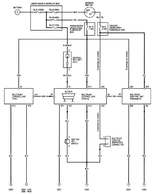
1: Using the wiring diagram identtify the plug/pins and wire for the commonication line between the nodes.
Between door unit and driver unit the commonication wire colur Brown and Pin NO A15 door and no 2 driver .
Between driver unit and passenger door unit wire color is Pink and Pin NO B1 for driver No 9 the passenger site.
2: Identify the plug/ pin and wire color for Earths and voltage supply line between the nodes.
Earth - A12 A19 Black, Voltage supply - A1 pink( Door Unit)
Earth - A14 B11 Black, Voltage supply - A1 white/black A12 pink A24 (Driver unit)
Earth - A8 B22 Black, Voltage supply - A22 yellow, A24 ( Passenger Unite)
wiring diagram:
Fault create by instructor:
The system was working , after asking the tuture to create fault after that the passenger door Windows system and center locking system does not works
Analyzing the fault:
There is open circuit or disconnected the commonication line between the driver unite and passenger unite . B1 pink which output from the driver unite B9 input passenger unite .
R/R and F/R coniction system is also connected from driver unite
Test mode 1
DTC Code # 2 the driver unite is not able to receive the signal from the passenger unite.
6: Do the codes concur with what you thought the problem might be from question 4, explain?
Yes, i agree with my answer with 4 because i said there is no communication between driver side unit and passenger side unit.
8. Conduct the tests in step 6, what is your results and conclusions?
My conclusion which i said in question 4, the communication line between the drivers side and passenger side was disconnected, because the other configuration which i have got. The center locking system is also controlled from the passenger side unit. Then we did test mode on manual that also tells us that system is faulty.
9. Put the system in to diagnostic Mode 2, conduct the input tests and note the results.
Multiplex Control Unit
(Passengers)
1 door switch
2 door switch
11. Using wiring diagram from the back of the manual describe what tests you would carry out now and what results you would expect. Note wire colours and pin/block numbers.
Pin number A15 in passenger unit, ground from passenger door switch which output from switch earth trigger.
12. Put the system in to sleep mode and measure the time it takes and the parasitic draw, Explain why this system is necessary.
It is important to know any open communication line or short communication line.


Sleep mode

Wake up mode
No comments:
Post a Comment